Showing posts with label Arduino. Show all posts

Saturday, December 31, 2016

Controlling lights with Bluetooth and Arduino


This simple design allows for a user to control their LED's or lights with the use of a relay. The circuit is pretty simple in which, there are only a couple of components; the Bluetooth module- the HC-06 , the Arduino module like a mega, Uno, nano or mini and extensions like a relay and transistor. The circuit can be used in many scenarios like wireless controlled appliances, room lights, fans and etc. As well these Bluetooth modules are cheap if bought online.
The photo on the left shows the HC-06 module with 4 pin-outs.

The photo below shows the circuit design:

Below is the simple code for Arduino:
For the blue highlight, change the integer value to change the pin-out used for the Arduino
Add multiple pinMode for more pins controlled

For the green highlight, change the character value to change the character eg. (1,2,a,b,c) needed to be received by the BT module to do an operation

For the yellow highlight, you can write more operation that it does if the character is received.

You can copy and write more jobs that the Arduino will do if a character is received.

#include <SoftwareSerial.h>
SoftwareSerial BT(10, 11);
void setup()
{
  pinMode(13, OUTPUT);
//eg.  pinMode(12, OUTPUT);
//eg. pinMode(11, OUTPUT);

  BT.begin(9600);
}
char a;
void loop()
{
  if (BT.available())
  {
    a=(BT.read());
    if (a=='1')
    {
      digitalWrite(13, HIGH);
    }
 
     if (a=='2')
    {
      digitalWrite(13, LOW);
    }

//Example of more code
//     if (a=='3')
// {
//    digitalWrite(12, LOW);
// }

//     if (a=='4')
//   {
//     digitalWrite(12, LOW);
//   }

  }

}


FOR THE APPLICATION USED TO CONTROL THE BLUETOOTH CIRCUIT
Download applications like "Bluetooth terminal" or "Arduino BlueControl" 
*Search up on google play store

In bluetooth terminal, you type in the value that you assigned for an operation and send.

In Arduino BlueControl, you can have variety of ways to control the module, but you would assign a button or arrow to the value that you assigned for an operation.

Monday, December 26, 2016

LED strip lights gradual fader


This LED fader circuit requires a Arduino device and a LED strip tape that is RGB colored. The photo on the side shows the cluttered breadboard holding the Arduino nano, mosfets and the LM7805 regulator. It is recommended to solder the components and solder a socket for the Arduino Nano onto a PCB board to maintain proper electrical connect. Typical application for this light circuit are Christmas Lights (which this was used for) and indoor house light decorations. The LED tape used here is a 5 metre roll of 5050 LED lights which was powered by a 12V 3 Amp power supply. The Arduino code cycles through many colors and the rate of change can be changed by changing the delay value in the code.
  The following picture shows the entire circuit diagram: 

Below is the Arduino Code that I found:

Change the integers of the orange highlighted part to change the pinouts of the Arduino
Change the integers of the yellow highlighted part to change the changes of color pattern
Change the integer of the turquoise highlighted part to change the speed of change

const int redled = 11;
const int greenled = 10;
const int blueled = 9;

void setup() {
  setColourRgb(0,0,0);
}

void loop() {
  unsigned int rgbColour[3];

  rgbColour[0] = 0;
  rgbColour[1] = 0;
  rgbColour[2] = 0;

for (int decColour = 0; decColour < 3; decColour += 1) {
int incColour = decColour == 2 ? 0 : decColour + 1;
    for(int i = 0; i < 255; i += 1) {
      rgbColour[decColour] -= 1;
      rgbColour[incColour] += 1;
   
      setColourRgb(rgbColour[0], rgbColour[1], rgbColour[2]);
      delay(20);
    }
  }
}

void setColourRgb(unsigned int red, unsigned int green, unsigned int blue) {
  analogWrite(redled, red);
  analogWrite(greenled, green);
  analogWrite(blueled, blue);

 }

Sunday, May 22, 2016

Using Arduino to measure volume of sounds


Above is the code that i wrote and modified. There are some extra line that aren't used or where placed for other purposes like the lines for the last IF and Else statement.

buzzer
The code above shows how an Arduino can be programmed so that it can measure the varied sounds and sound levels of its surroundings. It this code, it tells about when the level of sound is high a buzzer would sound, also a Led would light up whenever there is a reaction of noise in its surroundings. To read the sound levels, the code contains lines which tell it to send a word or a phrase to a computer through serial connection. These words are set to be transmitted whenever they reach a certain line of level of volume or frequency.  The parts used here from a grove kit for an Arduino Uno or others.

microphone with oamp


The hardware

Thursday, August 27, 2015

Brightness light sensor for Micro-controllers Using an LDR

Brightness Light Sensor for Micro-controllers
This circuit senses the brightness levels in the surroundings and converts it into a analog signal which the micro-controller converts and displays the brightness that it senses. This circuit works with Atmel Atmega device, Arduino and other micro-controllers. This circuit is basically a variable voltage divider. If the LDR senses more brightness, the voltage from the output decreases, the darker the LDR is in, the output voltage increases. Stay tuned for the code that I used for this light sensor with my Atmega micro-controller.
Above is what an LDR used in the circuit looks like.

Wednesday, August 26, 2015

Temperature sensor for micro-controller using an NTC thermistor

Temperature sensor for Micro-controllers

This temperature sensor is used for micro-controllers to measure a range of temperatures. This sensor uses the
( NCPppXH103) NTC surface mount thermistor. You can use any thermistor, but you must have the datasheet for that specific thermistor to get the thermistor resistance ratio in order for your micro-controller to be able to calculate the voltage into a temperature unit. This circuit above is basically a variable voltage divider, where the voltage on the output changes depending on the temperature. There is a ratio between the temperature and the resistance of the thermistor. This is how the micro-controller can calculate the temperature. The voltage that comes out from the output goes out to the ADC in the micro-controller. This sensor can be used with an Arduino or an Atmega chip or other micro-controller.

On the above left i have the surface mount thermistor on a piece of perf board which can be detached from my micro-controller.
In a later post i will show you how to make your own microcontoller and show the specs of my microcontoller.
On the left you can see the senor detached.
I have used the sensor, and its pretty accurate, but you have to do trial and error with the code. Stay tuned for the code with the sensor, where it can display the temperature on to a LCD display, but the this code is used with an Atmega chip and programmed with an Atmel Studio. I will post the code with arduino, later on.

Monday, August 24, 2015

10 led random pattern flashing using Arduino (Uno)

//Multi LED Blink

int led1Pin = 13;
int led2Pin = 12;
int led3Pin = 11;
int led4Pin = 10;
int led5Pin = 9;
int led6Pin = 8;
int led7Pin = 7;
int led8Pin = 6;
int led9Pin = 5;
int led10Pin = 4;

void setup() {  
  //initialize the led pins as an outputs
  pinMode(led1Pin, OUTPUT);
  pinMode(led2Pin, OUTPUT);
  pinMode(led3Pin, OUTPUT);
  pinMode(led4Pin, OUTPUT);
  pinMode(led5Pin, OUTPUT);
  pinMode(led6Pin, OUTPUT);
  pinMode(led7Pin, OUTPUT);
  pinMode(led8Pin, OUTPUT);
  pinMode(led9Pin, OUTPUT);
  pinMode(led10Pin, OUTPUT);

}

void loop() {
  //pick a random color
  analogWrite(led1Pin, random(256));
  analogWrite(led2Pin, random(256));
  analogWrite(led3Pin, random(256));
  analogWrite(led4Pin, random(250));
  analogWrite(led5Pin, random(256));
  analogWrite(led6Pin, random(256));
  analogWrite(led7Pin, random(256));
  analogWrite(led8Pin, random(256));
  analogWrite(led9Pin, random(256));
  analogWrite(led10Pin, random(256));
  delay(300);//wait one second


/*  digitalWrite(led1Pin, HIGH);//turn LED on
  delay(100);
  digitalWrite(led1Pin, LOW);//turn LED off
  delay(100);

  //do the same for the other 3 LEDs
  digitalWrite(led2Pin, HIGH);//turn LED on
  delay(100);
  digitalWrite(led2Pin, LOW);//turn LED off
  delay(100);

  digitalWrite(led3Pin, HIGH);//turn LED on
  delay(100);
  digitalWrite(led3Pin, LOW);//turn LED off
  delay(100);

  digitalWrite(led4Pin, HIGH);//turn LED on
  delay(100);
  digitalWrite(led4Pin, LOW);//turn LED off
  delay(100);


  digitalWrite(led5Pin, HIGH);//turn LED on
  delay(100);
  digitalWrite(led5Pin, LOW);//turn LED off
  delay(100);


  digitalWrite(led6Pin, HIGH);//turn LED on
  delay(100);
  digitalWrite(led6Pin, LOW);//turn LED off
  delay(100);


  digitalWrite(led7Pin, HIGH);//turn LED on
  delay(100);
  digitalWrite(led7Pin, LOW);//turn LED off
  delay(100);


  digitalWrite(led8Pin, HIGH);//turn LED on
  delay(100);
  digitalWrite(led8Pin, LOW);//turn LED off
  delay(100);


  digitalWrite(led9Pin, HIGH);//turn LED on
  delay(100);
  digitalWrite(led9Pin, LOW);//turn LED off
  delay(100);


  digitalWrite(led10Pin, HIGH);//turn LED on
  delay(100);
  digitalWrite(led10Pin, LOW);//turn LED off
  delay(100);
  */
}

Above is the code that i wrote which will randomly light colored leds at different times and different brightness. You can use this light code and these lights to light up a part and, if you expanded the code and light, you can light your room in different colored variation. In the circuit with the arduino, you would use pins 4 to 13. These are the pins that i used in the code. It doesn't matter which type of led goes where, but make sure to put a 100 to 200 ohm resistor in series with the led, unless you want to burn out your leds.

Below, is a video of the code lighting lights using the arduino uno and  10 leds with colors of  red, green and yellow.


Monday, August 10, 2015

Arduino 3 LED fading


Arduino 3 led color fading
The code above is to slowly fade 3 different led colors from one to another. This code will increase and decrease in brightness to transition to the next color. The circuit in this uses 3 different colored led with a 100 ohm resistor each led. Each led is connected to one of the Arduino's pins, the ones i used were 9, 10 and 11, like you see above in the code.
Above, you can see the video of the leds fading from one another with the Arduino code.

Below you can see how i have wired the leds with the Arduino. You can replace the led(s) with an RGB led, like you can see below.


Thursday, July 30, 2015

Using a 1x16 LCD Display with an Arduino (uno)

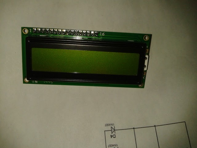
LCD Display
the arduino code above is the code needed to be inputed in an arduino (uno) to use a lcd display. The lcd that i have on the left is a 16 by 2 lcd display but the display is split in 2 havles, 8 on one side and 8 on the other side.
You can see in the top that the message i wanted to print was hello world  and after void loop, you can see that hello world is split in 2 parts because the display is split in 2 parts.
To know how to connect the lcd display to the arduino, look below.