Saturday, January 25, 2020

How to increase Lenovo laptop's battery life

A common issue on online forums for Lenovo Laptops are the battery life. Personally I have dealt with this problem on the Lenovo L340 Gaming Laptop. Most of Lenovo Laptops include a specification of around 7 to 8 hours of battery life for browsing, video watching and other day to day tasks. However, in forums, this battery life has been reduced to 2 hours from the high power draw from the processor and display. The following photos will describe ways to get a better battery life, of around 7 to 8 hours.

With the following modifications, it has led to 7 hours and 30 mins of browsing with just 86% power
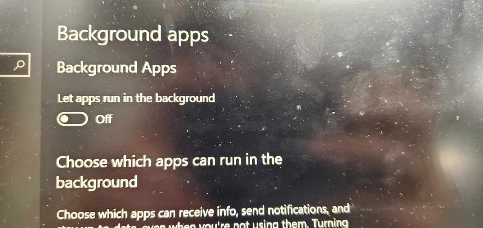
1. Turning off Background apps in the privacy setting on Windows 10. Turning this off will prevent any unimportant apps from running such as calculator, Skype and bloatware.

\
2. Going into control panel for battery management, additional power options can be chosen. When closing the laptop lid, or pressing the power button, the setting was changed from sleep to hibernate to preserve battery life while travelling. In addition, the graphics was changed to maximum battery life on battery mode.

3. One of the main settings that contributed to high power savings was minimum and maximum processor state. On battery mode, the minimum processor state was changed from 5% to 0 % and maximum processor state from 100% to 10%. On the L340, no major differences could be spotted by changing these settings, however did drastically increase battery life. Reducing the processor state prevents the CPU from being used to its fullest(draw the most power), thus benefits battery life and CPU lifetime.

Thursday, January 9, 2020

How to set up SSH with Raspberry Pi and PuTTY


The Raspberry Pi, a miniaturized computer provides an ability to complete many tasks on such a small device. In this post, the Raspberry Pi 3B used will be running Raspian as it is the most common free operating system. Sometimes when typing on the command prompt, it may be tedious to do certain tasks typing on the Raspberry Pi and multitasking on other sites. This is where utilizing the Raspberry Pi's SSH allows for users to remotely type on the Pi's command prompt from just a laptop. This provides the ease of multitasking and using the clipboard.
To enable this feature, the preferences in the Raspberry Pi must be changed:
Going to the start menu, and into preferences will show Raspberry Pi configurations button.
Clicking onto that, and going into Interfaces, the SSH must be enabled.
Now the Raspberry Pi has been accommodated to use SSH.

On the computer side, PuTTY must be downloaded from the site https://www.putty.org/.
Click on the here link on that page.
Now this brings you to the available files that can be downloaded. Choose the appropriate file for your operating system, either 32 or 64 bits.
Click the file once it is downloaded to run the installation process.

(In the installation process, a box can be checked to create a desktop icon for PuTTY)

Opening the application will look like this.
Now making sure the Pi is connected to the same network as the computer, look for the Raspberry Pi's IP address. In my scenario, I opened a hot spot which allowed my Raspberry Pi to connect and easily reveal the IP address. In other situation, utilizing a free app called Fing, will allow you to see all the IP addresses of the devices connected to the network.

With the computer hot spot setup, the IP address of the Raspberry Pi will be shown.
Now copy the IP address into the spot that says Host Name (or IP address).
The IP address can be saved with a corresponding name (Raspberry was used above)
Clicking Save will show the session stored underneath Default Settings.
To open the SSH connection, double click on the saved session or click open.
This will be the screen after the connection is opened. 
In all Raspberry Pi's there is a default login id and password which is required to connect.
The default id is pi.
The default password is raspberry. (When typing in the password, the password will not show on screen nor move the cursor, so don't be alarmed)

After the connection is established, this is what the final screen should look like. Now you can directly type into the command prompt of the Raspberry Pi from a computer.

Wednesday, January 8, 2020

Fixing Quality of 3D Prints

On the left illustrates the progression of the quality of 3D printed cubed. Going down the photo, the cubes progressively become more precise and neater. The factors that were resolved or reduced were ghosting, stepper motor calibration, acceleration, jerk and replacement of the nozzle.

Ghosting: (cube 1 and 2)
The term referring to the subtle disruptions in the printing lines are clearly shown in cube 1 and 2. The ghosting effect is caused due to vibration of the motors, causing the extruder to subtly wobble while printing. This issue can be resolved by using foam pads on the bottom of the printer's feet to absorb shaking.

Stepper motor calibration: (cube 2,3,4)
This was an issue which would resolve over or under extrusion issues in the prints. In the imperfect prints at the top, bulges around the print can be observed. These bulges can be the result of over extrusion, when the extruder pushes more filament out than it should.

Acceleration and Jerk:(5)
In a custom/ commercial printer, the acceleration and jerk settings can be changed so that the print speeds can be increased. However, with these settings increased, it can result in a poor quality print found in the black cube. Reducing the acceleration in a Cartesian printer to around 500 and the jerk to around 10 for the x,y, and z axis produced better results. In addition, increase the retraction acceleration seemed to have benefited the prints.

Nozzle Replacement: (cube 6)
The printer used to print the black cube has have over a year of printing, thus leading to a degrading of the nozzle and the quality of the nozzle diameter. This degradation can lead to inconsistent printing pressures and thicker print lines. In the last print, a new 0.4mm nozzle is used, and it obviously shows a greater improvement. *A different file was used in cube 6 to demonstrate the finer detailed print of smaller spacer

Friday, January 4, 2019

Replacing Hub motors on personal electric skateboard

In this project, my modified skateboard needed its hub motor wheels changed. The wheels are shown on the left and below. They show the wheels severely damaged and weathered after around 200 km of use.


The old hub motor was removed and the new red hub motor was installed which was bought on Ali-express.

The main power wires were connected to the correct colours of yellow to yellow, blue to blue and green to green.
However, the hall sensors connectors for the hub motors are connected in a different sequence. This is shown below. The correct sequence was identified by trial and error. This trial and error did not damage the circuitry. But do try on your own risk.


Adding wireless charging to a power bank

The purpose of this project is to add wireless charging to a typical power bank. This addition to the power bank will provide ease of charging without the hassle of cables moving around. This project can only be done to power banks with a plastic case. The wireless receiver and wireless transmitter can be obtained from Ali-express for only a couple dollars. The original wireless receiver shown on the far left had a micro USB plug for my phone but had unfortunately broken off. This receiver was re-purposed for this project.
The power bank was carefully opened up with a non-metallic pry tool. Do this project at your own risk. Lithium cells can be easily punctured and start a fire or explode.

There was a + and - connection on the wireless receiver, which was carefully soldered to the input pins of the micro USB port of the power bank.


On the right shows that the power bank properly charges with the wireless charger.


 The power bank continues to charge with the case reattached.

Saturday, December 1, 2018

Modifying the Solar Energy Hub~ Faster Charging


In the above photo displays the Solar Energy Hub. This unit was personally modified as the Solar Input on it was not responsive all the time, as well as causing slow charging issues. Another aspect that was modified was the USB phone charging port, where it was only able to supply a constant current of 500Ma at 5.00v. This power output was not enough to charge modern phones which require a minimum of at least  1.0 to 2.0 Amps at 5.0V.  On the left shows the unit before modifications.
Underneath to the left shows the unit after the modifications. Two active components installed was the XL0009 Variable Step Up converter and the TP4056 Li-ion Protection Board. The XL009 was connected in parallel with the Phone Charging USB Port, and was calibrated to 5.0V to suits phone charging specs.

A Switch was installed in on the unit which was in series with the Step Up board to prevent discharge over a long period of time

XL009 Step Up Board
The Step Up board can Step up Voltages from 3.0V to 30 V at around 3 to 4 Amps depending on Heat Dissipation. The potentiometer on the board allows for variable Voltage changes.
TP4056 Protection Board
The TP4056 has 3 pairs of connections. First for Charging Input shown the left red green wires. Second for Battery Input and Third for Battery Discharge. When the Voltage of the Battery Reaches a certain threshold, the board will disconnect the battery from the load, saving the battery from overdischarge.

Monday, June 25, 2018

Version 1 Solar Charger and Load controller


Above shows the basic diagram of how a charge controller should be wired up. On each of the connections, there is a switch to allow for closing and isolating a section of the charge controller. On the picture on the right is a prototype on how it all planned out. In addition, the left picture also includes 10 amp fuses on each of the sections of the charge controller to prevent any short circuits or overloads from damaging the components.
However, in the version one, the bus bar used was an aluminium bar, which proved to cause too much resistance in the circuit. This large resistance caused for a drop in voltage and create inaccurate voltages read by the charge controller. The bar shall be replaced with a more electrically conductive material to increase efficiency. As well, the current size of the project is too large, so version 2 will be condensed down. Even though this circuit had power losses. For 2 years, the circuit had run smoothly and resulted in 3000 accumulated amp hours in charging and 2000 accumulated amp hours in discharging.

Saturday, December 31, 2016

Controlling lights with Bluetooth and Arduino


This simple design allows for a user to control their LED's or lights with the use of a relay. The circuit is pretty simple in which, there are only a couple of components; the Bluetooth module- the HC-06 , the Arduino module like a mega, Uno, nano or mini and extensions like a relay and transistor. The circuit can be used in many scenarios like wireless controlled appliances, room lights, fans and etc. As well these Bluetooth modules are cheap if bought online.
The photo on the left shows the HC-06 module with 4 pin-outs.

The photo below shows the circuit design:

Below is the simple code for Arduino:
For the blue highlight, change the integer value to change the pin-out used for the Arduino
Add multiple pinMode for more pins controlled

For the green highlight, change the character value to change the character eg. (1,2,a,b,c) needed to be received by the BT module to do an operation

For the yellow highlight, you can write more operation that it does if the character is received.

You can copy and write more jobs that the Arduino will do if a character is received.

#include <SoftwareSerial.h>
SoftwareSerial BT(10, 11);
void setup()
{
  pinMode(13, OUTPUT);
//eg.  pinMode(12, OUTPUT);
//eg. pinMode(11, OUTPUT);

  BT.begin(9600);
}
char a;
void loop()
{
  if (BT.available())
  {
    a=(BT.read());
    if (a=='1')
    {
      digitalWrite(13, HIGH);
    }
 
     if (a=='2')
    {
      digitalWrite(13, LOW);
    }

//Example of more code
//     if (a=='3')
// {
//    digitalWrite(12, LOW);
// }

//     if (a=='4')
//   {
//     digitalWrite(12, LOW);
//   }

  }

}


FOR THE APPLICATION USED TO CONTROL THE BLUETOOTH CIRCUIT
Download applications like "Bluetooth terminal" or "Arduino BlueControl" 
*Search up on google play store

In bluetooth terminal, you type in the value that you assigned for an operation and send.

In Arduino BlueControl, you can have variety of ways to control the module, but you would assign a button or arrow to the value that you assigned for an operation.

Monday, December 26, 2016

LED strip lights gradual fader


This LED fader circuit requires a Arduino device and a LED strip tape that is RGB colored. The photo on the side shows the cluttered breadboard holding the Arduino nano, mosfets and the LM7805 regulator. It is recommended to solder the components and solder a socket for the Arduino Nano onto a PCB board to maintain proper electrical connect. Typical application for this light circuit are Christmas Lights (which this was used for) and indoor house light decorations. The LED tape used here is a 5 metre roll of 5050 LED lights which was powered by a 12V 3 Amp power supply. The Arduino code cycles through many colors and the rate of change can be changed by changing the delay value in the code.
  The following picture shows the entire circuit diagram: 

Below is the Arduino Code that I found:

Change the integers of the orange highlighted part to change the pinouts of the Arduino
Change the integers of the yellow highlighted part to change the changes of color pattern
Change the integer of the turquoise highlighted part to change the speed of change

const int redled = 11;
const int greenled = 10;
const int blueled = 9;

void setup() {
  setColourRgb(0,0,0);
}

void loop() {
  unsigned int rgbColour[3];

  rgbColour[0] = 0;
  rgbColour[1] = 0;
  rgbColour[2] = 0;

for (int decColour = 0; decColour < 3; decColour += 1) {
int incColour = decColour == 2 ? 0 : decColour + 1;
    for(int i = 0; i < 255; i += 1) {
      rgbColour[decColour] -= 1;
      rgbColour[incColour] += 1;
   
      setColourRgb(rgbColour[0], rgbColour[1], rgbColour[2]);
      delay(20);
    }
  }
}

void setColourRgb(unsigned int red, unsigned int green, unsigned int blue) {
  analogWrite(redled, red);
  analogWrite(greenled, green);
  analogWrite(blueled, blue);

 }

Sunday, May 22, 2016

Using Arduino to measure volume of sounds


Above is the code that i wrote and modified. There are some extra line that aren't used or where placed for other purposes like the lines for the last IF and Else statement.

buzzer
The code above shows how an Arduino can be programmed so that it can measure the varied sounds and sound levels of its surroundings. It this code, it tells about when the level of sound is high a buzzer would sound, also a Led would light up whenever there is a reaction of noise in its surroundings. To read the sound levels, the code contains lines which tell it to send a word or a phrase to a computer through serial connection. These words are set to be transmitted whenever they reach a certain line of level of volume or frequency.  The parts used here from a grove kit for an Arduino Uno or others.

microphone with oamp


The hardware

Saturday, January 30, 2016

How to wire the LCD pinouts for the Atmega88p

Above shows the Pinout of where and what the 1x16 LCD Screen is connected to for the Atmega88p LCD code. The pinouts on the LCD screen show the parts of the LCD and the Legend shows where the pinouts of the LCD are connected to the Atmega88p.

Atmega88p code for a 16x1 LCD Screen


The pictures above uses the code below. The LCD screens are 1 by 16  and are split into 2 parts of 8.
Replace the pink XXXXXXXX, with the desired words, but remember, the screen is split in 2 parts.


//#define F_CPU         4000000UL
#include <avr/delay.h>
#include <avr/io.h>

/*LCD function declarations */
void LCD_send_command(unsigned char cmnd);
void LCD_send_data(unsigned char data);
void LCD_init();
void LCD_goto(unsigned char y, unsigned char x);
void LCD_print(char *string);
void LCD_blink();
void LCD_scroll(unsigned char direction);

#define LCD_DATA_PORT PORTB
#define LCD_DATA_DDR   DDRB
#define LCD_DATA_PIN     PINB

#define LCD_CNTRL_PORT           PORTC
#define LCD_CNTRL_DDR DDRC
#define LCD_CNTRL_PIN   PINC

#define LCD_RS_PIN                       0
#define LCD_RW_PIN                     1
#define LCD_ENABLE_PIN            2

int main(void)
{
DDRD =0xFF;
PORTD|=1<<0;
PORTD|=1<<1;
PORTD|=1<<2;
PORTD|=1<<3;
PORTD|=1<<4;
            unsigned char i;

    LCD_init();
            LCD_goto(1,1);
            LCD_print("XXXXXXXX");
            LCD_goto(2,1);
            LCD_print("XXXXXXXX");
      
}

/* This function sends a command 'cmnd' to the LCD module*/
void LCD_send_command(unsigned char cmnd)
{
            LCD_DATA_PORT = cmnd;
            LCD_CNTRL_PORT &= ~(1<<LCD_RW_PIN);
            LCD_CNTRL_PORT &= ~(1<<LCD_RS_PIN);

            LCD_CNTRL_PORT |= (1<<LCD_ENABLE_PIN);
            _delay_us(2);
            LCD_CNTRL_PORT &= ~(1<<LCD_ENABLE_PIN);
            _delay_us(100);
}

/* This function sends the data 'data' to the LCD module*/
void LCD_send_data(unsigned char data)
{
            LCD_DATA_PORT = data;
            LCD_CNTRL_PORT &= ~(1<<LCD_RW_PIN);
            LCD_CNTRL_PORT |= (1<<LCD_RS_PIN);

            LCD_CNTRL_PORT |= (1<<LCD_ENABLE_PIN);
            _delay_us(2);
            LCD_CNTRL_PORT &= ~(1<<LCD_ENABLE_PIN);
            _delay_us(100);
}

void LCD_init()
{
            LCD_CNTRL_DDR = 0xFF;
            LCD_CNTRL_PORT = 0x00;
            LCD_DATA_DDR = 0xFF;
            LCD_DATA_PORT = 0x00;

            _delay_ms(10);
            LCD_send_command(0x38);
            LCD_send_command(0x0C);
            LCD_send_command(0x01);
            _delay_ms(10);
            LCD_send_command(0x06);
}

/* This function moves the cursor the line y column x on the LCD module*/
void LCD_goto(unsigned char y, unsigned char x)
{
            unsigned char firstAddress[] = {0x80,0xC0,0x94,0xD4};

            LCD_send_command(firstAddress[y-1] + x-1);
            _delay_ms(10);          
}

void LCD_print(char *string)
{
            unsigned char i=0;

            while(string[i]!=0)
            {
                        LCD_send_data(string[i]);
                        i++;
            }
}

void LCD_blink()
{
            LCD_send_command(0x08);
            _delay_ms(250);
            LCD_send_command(0x0C);
            _delay_ms(250);
}

void LCD_scroll(unsigned char direction)
{
            if(direction == 0)
                        LCD_send_command(0x18);
            else
                        LCD_send_command(0x1C);

            _delay_ms(500);

}

How to make a 12V PIR motion light with 5v PIR module, a mosfet and NPN transistor Part 2

In the circuit above, it is just a modification of the part one circuit, replacing the PNP transistors with a N-channel mosfet and a NPN transistor. The circuit can be used with voltages from 8V-20V, using the LM7805, regulating the voltage to 5v for the PIR Module. The output of this circuit is controlled by the N-channel mosfet with controls the negative rail. To vary the time that the mosfet stays on, you would increase the capacitance of C1 and C2 for a longer ON time, but it would take a longer time to turn on( about 3-5 seconds), if you decrease the capacitance of the 2 capacitors, it would decrease the ON time, and the time from trigger to turning on would decrease as well.
The side and bottom picture, shows the circuit in place to act as a hallway motion light.


Saturday, January 16, 2016

How to make Pir Motion lights with npn and pnp transistors Part1

 Pir Motion lights
The circuit shows a PIR module connected to a npn and pnp transistor and a relay. This configuration allows, lights to be turned on when the PIR module sees an infrared pattern occur (when a person or warm blooded mammal goes in front of the module.With the 2 1000uf capacitors, the module turns on and stays on for about 1 minute. To increase or decrease the length of time, you would reduce the capacitor ratings to decrease time and increase capacitor capacity to increase time.
The diagrams below, show the pinouts of 2n2222 and 2n2907.


Pir Module